
This page refers to an old project. Recently I made a new attenuator design, which is now available!
This page shows my audio volume control circuit and implementation. The circuit provides both audio volume and input channel selection. A stepwise volume control is implemented with a set of tiny relays and resistors. In a high-end audio system, a noticable sound improvement over potentiomeneters is obtained, also compared to 'audio grade' potentiometers. Its IR remote control provides convenience over solutions with stepped attenuator rotary switches. The sealed relays will maintain contact quality over a practically endless lifetime. The design represents a audio 'preamplifier' of top-class sonic quality, in a compact and affordable implementation. However, its passive nature results in a quite high output resistance, which limits general applicability.
The design uses high-quality relays, and provides PCB space for somewhat larger audio-grade resistors. Normally I will provide RN60D mil-class resistors manufactured by Vishay-Dale, which have an excellent reputation for audio. In some tests by me, these indeed perform better than other good-quality industry-standard resistors. Of course you are free to apply more costly 'audiophile' resistors: I will be happy to learn about such results. The circuit targets high-end audio applications, particularly including tube-amplifier enthousiasts who prefer to avoid semiconductors in their signal path. However, very good sonic results have also been obtained with driving modern class-D amplifier modules.
This website provides schematics and documention, targetting DIY audio enthousiasts. This reflects my own involvement in 'audio' as hobbyist, although I attempt to create professional-quality things. Others are hopefully inspired, and create their own solutions, which I will happily learn about. To share my results, I also provide this design in limited quantities as a DIY building kit, see below. However, I do not freely distribute the firmware that is embedded in the microcontrollers: that gives some protection to my design, to support others who are interested in making a commercial derivative.
This attenuator design has the following features/characteristics:
The circuit tries to avoid clicks/glitches in the audio output signal while making volume steps,
due to carefully switching relays 'off' before others 'on'. However, you can clearly hear the
mechanical activity of the relays. If you don't like that, relays are not your solution.
For a closer look on the attenuator theory look here.

|
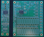
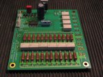
In kit form, you would receive the front- and relay-PCB, each with a pre-mounted and programmed microcontroller. The PCBs have a gold-finish for all solder areas, which gives a great look, easy soldering, and might even help for sonic quality. The front PCB handles the IR signal decoding and 7-segment display control, the relay PCB handles the audio. The kit provides all other components to be mounted on the PCBs for your own soldering. |

|
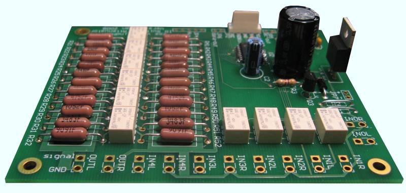
The fully mounted 'relais' PCB. The tiny G6K-2P relays behave fine for audio. The diodes, voltage regulator IC, and elco provide a 5V supply voltage. At the right side, the audio I/O can be wired. At the left side, the PCB has mounted a 2-pin connector for its 6V-7Vac power input and a 5-pin connector for the display PCB. |

|
The mounted front PCB. The two-digit 7-segment display gives feedback on the current volume setting and input selection. This switch also provides a push-button action, such that every press selects the next input channel. You find the black IR sensor mounted just right from the center. Clearly, the wires between the PCBs do not carry any audio signals. The rotary switch is for manual volume up/down. It is non-blocking with 30 clicks per full turn. With my new version (as of Febr. '08), I provide a good-quality Alps switch with a metal housing (different from neighbouring foto). This Alps switch is also suitable for front-panel screw-mounting, separated from the PCB. |

|
Full schematics of the design, in a 2 page pdf document. Note that the circuit consists of three sections that are totally isolated from each other, each having separate grounds: 1) The control with the microcontrollers, display, power supply, and relay coils, 2) Left channel audio resistors and relay contacts, and 3) Right channel audio resistors and relay contacts. This allows your choice of grounding scheme when building your system. |

|
User guide text in pdf, revision Jan. 2009. It contains assembly guidelines, and instructions to learn the device to recognise the button codes of your IR remote handheld. Recognisable buttons (IR commands) are volume up and down, mute, input channel up and down, numeric selection of input channel, and power off. Clearly, remote power on/off only works for other equipment, when this controller remains powered. If the controller itself is switched off, it will remember its last settings (volume and input channel) in embedded EPROM, and will load those settings again when powered on. (Previous revision of userguide, Feb. 2008.) |

|
Datasheets of all the components that I used in a zip archive. You might look in here to check pin connections, or check compatibility with other part types. (Well, to save on my webspace, all component datasheets except for the PIC16F819-I/SO microcontroller which you can easily find at the Microchip website.) |
Upon request I can provide you (interested hobbyist) with parts for this design.
The PCB with a complete set of components for a stereo setup costs €140,=.
This includes relais, the 'Dale' resistors, rotary switch, display, and all other PCB-mount components,
but excludes audio cinch connectors and housing.
An extra slave board to support balanced audio or multi-channel will be €100,=.
I would pre-mount both (SMD type) microcontrollers and program them with my firmware.
All other components are provided as is, for traditional through-hole mounting.
For sending a kit inside the Netherlands or though Western-Europe I ask €10,=,
for 'sign on receipt' delivery. You can ask me for other destinations....
If you
me, please use the word 'attenuator' in the subject.
Unfortunately, I have received many more requests on this design than I can handle.
(Note that I do this as hobby project...)
Currently there is a waiting list in my mailbox which exceeds the number of kits I still have here.
As I first want to complete some of my other projects, I do not intend to make a new set of kits available anytime soon.
As alternative, you can buy this design as pre-assembled module at: http://www.tentlabs.com/Products/page31/page31.html
These are a few pictures that I received from earlier attenuator builders...
Note: More recently I made a design for a complete preamplifier, for balanced audio with an active output buffering: RelaiXed2. Later, this was followed by a more compact version: RelaiXedSMD. Both these designs employ techniques to smooth the edges on the switching of the volume-relays, overcoming the old problem of clicks in the audio output. The latter more compact design also allows a passive implementation. Both these designs use the same controller for which the source-code is made public.